Designing for 3D printing
Here's some thoughts and suggestions on ways to improve your prints by designing them in a way that makes them easier to print.
Expect slightly rounded corners
Since the printer nozzle is round it is impossible to create a perfectly sharp outer corner on your parts. Depending on your print speed there's also a very good chance that you'll get some additional oozing at the corners since the print head needs to slow down in the curve. During the slow down the builtup pressure in the nozzle causes some excess plastic to sneak out creating a slightly thicker extrusion.
This picture shows the effect. This corner was designed to be perfectly square in CAD but as you can see the machine is not capable of creating this edge. What's worse is that there is some slight material build up.

Now, the corner become slightly rounded is probably not a problem in most cases. But what if you were trying to make a square part fit into a square hole, such as a lid? This extra build up could prevent that from being possible without adding additional clearances all around the part.
Because of this it can be a good idea to make the corners or your parts slightly rounded at the design stage. This way you'll have better control over it.
Print in place
Given that objects in a 3d printer are built layer by layer there are some interesting things you can do by taking advantage of this fact. One such thing is to print assemblies in place. That is, instead of creating multiple separate pieces that you then mount together, you can (in some cases) print the pieces already assembled.
The biggest challenge when creating designs for this purpose is to make sure that the different parts do not stick together and are unable to move relative to each other. This is mostly a problem on the areas of the print where one part is lying on top of another. It is much harder to control a strand of plastic that is extruded into mid air as it will sag unpredictably. Because of this it is important that you leave enough clearance between the two parts to allow of this sagging. How big that clearance needs to be is difficult to give a straight forward answer to.
If the overhanging part is very small, say 10mm across, you may get away with a clearance as small as 0.5mm. If it's longer or if it has an intricate shape you may find that it sags down considerably more and you'll have to compensate for this accordingly. By far the easiest way to figure out how much you need is to simply print out a test piece and see what happens. Create a small test part so that you don't have to waste more time and plastic than you need.
In the example below is a hinged dust filter that is printed as a single piece. The top part of the image shows the entire part while the lower image shows a section cut of the hinge. As you can see we've respected the 45degree rule by making the overhangs of the hinge stay at 45 degrees. This makes it easy for the printer to handle but we also completely avoid the problem of sagging that could cause the two parts to fuse. 
In the X-Y direction this isn't nearly as big a problem and you can design parts with quite tight tolerances. We've created parts with as little as 0.2mm of clearance. The one problem that you may run into is with stringing which can cause the parts to fuse together. You can read more about stringing and what you can do to lessen its impact here.
Of course you're not limited to creating parts that interlock or interact directly. One very common example is the whistle where the little ball is printed inside of the whistle from the start. After the print is done the ball is simply broken free from the rest of the print and is free to rattle around inside of it.
Complexity is "free", make use of it
What we mean by this is that the printer doesn't care if it creates a cube or an intricate set of shapes. Granted, a simple cube doesn't use any retraction or many travel moves to speak of, so print time will be slightly lower. But if we simplify things a bit, complexity is "free".
The classic example used for this is parts designed for commercial airplanes such as the bracket below. Since we are not limited by what shapes we can cut out of a solid chunk of metal we can optimize the shape and get rid of material.

Something else that you are not able to do with traditional manufacturing is designing voids into your model. To save weight you can create completely hollow parts, or hollow out areas of a part. By placing these voids in strategic places you will reduce material usage, reduce the weight of the part and still retain strength. In traditional manufacturing you can do something similar by drilling/milling away areas of the part, but with 3d printing you can hide them from view. And since you have a thin "skin" over the holes it will also aid in strength.
Joining large pieces
Even though the print area of an Ultimaker and Ultimaker2 is quite spacious there is of course a limit and to go bigger you'll have to break your print up into several pieces and join them together. There are a multitude of ways to accomplish this. The most straight forward is of course to just simply glue the parts together. This works well but you're using a 3d printer, complexity comes more or less free as far as the printing goes. So, why not get creative with it?
But to go back to glueing for a second. To aid with this it's a good idea to add alignment holes and pegs to your parts. A simple round hole and a round peg is usually enough to make sure your parts align correctly and stay in place while the glue hardens. It also aids a bit with structural integrity as it will help prevent the parts from shearing apart.
If you are joining a thin standing piece to a larger piece, say a wall, you can also print guides to aid in keeping the part square with the other print. Create a couple of locating holes to keep the part at the correct location and then create a thin, breakaway, guide in the correct location to keep the part square.
If glue isn't your thing you could consider taking a few hints from the wood working world. Dove tail joints are widely used in wood working and there's no reason you can't use it for your 3d prints as well.
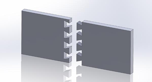
Since complexity is essentially free you could even design threads to join the parts together, permanently (by adding some glue) or temporarily.
Assemble rather than print all at once
Don't be afraid of printing in more than one part. While it's attractive to print a large piece, snap it off the platform and be done, sometimes it's not the best way to go. There's a couple of good reasons to print something in several parts. For one, you might be able to get rid of support which, let's face it, is a pain to remove a lot of the time. Another reason which might be more important to you depending on what you're making, is strength.
Let's start with the first one. As you probably know already, overhangs are difficult to print. Of course your best bet is to try and design your model in such a way that overhangs are eliminated. But if that's not possible you can break up your model into several sections and orient them in such a way that the overhangs are no longer a problem.
Here's an example of a shape that will be difficult to print in one part no matter what orientation you choose. You'd have to add and remove a lot of support material to be able to finish that print. However, if you simply break it into two parts it suddenly becomes very easy to print and all you have to do is put it together with some glue. Also note the locating hole and peg. I've also added some fillets and chamfers to make it easier to insert.

Strength is another good reason to maybe break things up. If you print thin column standing up on the bed you'll be able to very easily snap it, print it lying down and it will be much stronger. So what you want to do then is of course to orient the parts to take advantage of this.
Chamfer/Fillet edges to reduce stress points
Say you're creating an object that is a cylinder on top of a box. Where the cylinder joins to the box there's a sharp transition and this is where the part will break when it is subjected to loads tangent to the cylinder. By putting a radius at this point you will make the part stronger. It will still break at the same point but it will be made stronger.
By putting a radius here you will also create a bigger base of solid infill for the cylinder. cura will only put solid infill on an area slightly larger than the cylinder underneath it. With the radius you increase this area ever so slightly aiding in strength further.

Include hardware for strength or utility
At the end of the day these printers are making parts out of plastic and no matter how fancy the plastic, metal will likely be stronger. Why not mix the best of both worlds? With the built in plugin "Pause at Z" it is easy to automatically stop mid print, add hardware and then resume the print. A great use for this is to drop in nuts to give screws a real metal thread to screw into. While you could tap a hole in the plastic using either a proper tap or by using the screw and friction to form a thread, you can't beat metal to metal.
Remember that a screw can create some serious torque so make sure you have enough material holding the nut in place to be able to resist the amount of torque you're planning to put on it. You could also consider strengthening the area around the nut by either printing more perimeter lines or by tricking the slicer into creating solid infill where needed.
Dealing with horizontal holes
Horizontal holes through a model will cause a severe overhang to form at the top of the arch. This means that, generally, a horizontal hole will be a bit squished at the top and therefore smaller than intended. There's a couple of things you can do to combat this.
The first approach is to change the shape of the hole by making the hole look more like a cartoon waterdrop. This makes it easier for the printer to handle and you get a bit of a margin for error so to speak for any droopage.
You might not like the aesthetics of that approach, so another thing you can try is to create a thin support membrane to help hold up the top of the hole. Rather than covering the entire hole it's a good idea to make the support narrow at the bottom and let it grow towards the top of the arch. This makes it very easy to snap off.

If the hole isn't so much for the looks but more for practical uses you may also consider experimenting with different hole shapes alltogether. How about a triangle or a square with one of the corners pointing up? These would probably mostly be useful for smaller holes though as it would leave quite a gap on the sides of the screw.
Force "solid" infill where needed
Most of you reading this guide will be using cura to prepare your parts for printing. At this time cura does not allow you to use multiple settings for infill in a single print. If you have a part where you need extra strength in just a small area of the print, such as around a fastener, you will have to increase the amount of infill or perimeters for the entire print.
A trick you can use to get around this is to create geometries that forces cura to put down more plastic in the areas you need. The way to do this is to simply pierce the area with a group of cylinders. This will cause cura to print a bunch of perimeter lines around the cylinders which in effect will fill in the area more densely.
Here's an example of what will happen. This is of course a silly example, just a box with some random extra infill, but it shows the principle. In this case we used 0.5mm diameter cylinders spaced 1mm apart but you should experiment with spacing and size to fit your specific needs. If the cylinders do not pierce the outer surface it could happen that weird things happen. You might have to play around with the "Fix horrible" settings in cura if the cylinders disappear on you during the slice. Always check layer view before printing to make sure you're getting what you're expecting.

Here is another example where we've added a bunch of holes in a circular pattern around the mounting hole in the model. As you can see the infill isn't completely solid but it's a lot more solid than the hole on the right that is "untreated".

Again, you could of course simply increase the wall thickness in cura to achieve a similar result but there might be times where this is a better approach. If you have a very large model for example where only a very small section needs the additional strength this method could save a lot of print time.
Round corners to reduce warping
Warping happens more at sharp corners which is where the stresses in the part will be the greatest. By rounding off corners you will reduce this effect slightly.
Optimize orientation for strength
To make it easier to understand the strength of your printed parts it helps to think of them as if they were made of wood. If you've ever chopped wood you know that it is very easy to split a log along it's length but if you try it the other way you'll be hacking away for ages. Similarly if you have a thin sheet of wood it can bend and flex on one direction but if you bend it in the other it will split along the grain of the wood.
Apply the same kind of thinking to your prints. Orient and design them in such a way that they are always as strong as possible. If you have a complex part with several pieces jutting out it might be a good idea to actually break your part up into several pieces that you assemble after printing. You might even save time doing this as you may be able to avoid printing any support at all.
Print out a size reference
Now this isn't so much a specific modelling tip, more of a good thing to think about tip. As mentioned elsewhere things that are printed tend to shrink as they cool down. This is especially problematic for small holes. To help with this you need to scale your holes/geometries to compensate. With time you'll start to get a feel for this and know instinctively about how much you need to compensate.
Also worth mentioning is that if your model has a very low poly count this will also make a hole smaller. Since a hole is represented by a series of straight lines a low poly count means that the lines will encroach on the diameter of the hole. This usually doesn't amount to much, but it's something to keep in mind.
But to make it easier on yourself you can model and print a reference for yourself. Create a model that has a series of holes, each slightly larger than the last, both horizontal and vertical. This way you can easily try to insert whatever you're modelling the hole for in the reference and know what size to use.
Manifold, what's that and why is it important?
A model that is not "manifold" is a model that can't exist in the real world. It could be that there are edges or vertices in the model are disconnected and floating in space, you could have an internal face or you could have areas with zero thickness. It is also common to refer to it as models that are not "water tight" which could be caused by holes in meshes for example.
It is important to fix these issues as they will confuse your slicer and could make it produce very unpredictable results. cura has a number of "Fix horrible" settings in the expert settings dialog that can work around these issues. There's also a free tool from Netfabb that can repair models, you can find it here.
It may also be possible to change the export settings in your CAD program to help guard against this. Things like the resolution of the exported model can be a factor.
Wall thickness
If your model contains thin walls it's a good idea to make them a multiple of your nozzle width (0.4mm for the UM2). If you make the walls thinner than a single line width there's a chance that cura will remove it from the model completely if it thinks it can't properly print it. Cura does a few tricks to be able to print both thinner and thicker lines than 0.4mm but if possible it's better to keep to multiples of 0.4mm since the nozzle was designed to print that width.
Also keep in mind that a sloped wall that measures Xmm perpendicularly to the surface will actually be wider when sliced in the horizontal direction.
The 45 degree rule
When designing a model you should try to keep overhang angles to a maximum of 45 degrees. The printer is capable of printing much worse angles than this but if you're looking for surface quality you want to limit the angle as much as you can. The steeper the angle the worse the quality will become.

In the picture above we show how you might design a model to make it as easy to print as possible. The first image shows that the upper part of the model has an obvious overhang that must be supported if it is to have any chance at all of getting printed properly. You can certainly print this using supports and you can read a bit more about that topic in the next section.
The middle of the image shows how we've changed the overhang angle to 45 degrees to make the part easy to print. Now, of course this isn't always possible. In the part above there might perhaps be intended that a belt is supposed to run in the middle which would either not fit or might slip out without a hard edge to keep it in place.
In the third variation we've broken the part in two and added a locating pin and hole so that the part can be glued together after printing. This approach means we can keep our hard edges and we wont scar the part by using support structures.
This is of course a very simple example but it shows the thought process on how you might go about adjusting your model to get the best result possible.
Design custom supports instead of relying on auto generated to lessen surface scarring.
Whenever you have areas of an object that is suspended in mid-air you will usually need some form of support. The good thing about supports is that they allow you to print things that would normally be impossible. The bad thing is that they will scar the surface of your print to varying degrees.
The support can either come from you or from an auto generated set of supports. cura has the ability to generate supports for you automatically. These supports usually do the job but can sometimes be difficult to remove and will usually leave ugly marks on your print. Another alternative is to use a separate program and for that there's a program called Meshmixer that is good at generating supports for organic models in particular. While cura generates a "block" of support structures underneath the overhang Meshmixer instead tries to use as little material as possible by creating support pillars. A great guide to using this program can be found here.
But the best alternative might be to manually create the support when you design your model. Humans are still smarter than computers in this area and can be a bit more selective with how the support should be constructed. That way you can save both printing time and plastic. You might also be able to better hide any ugly interface layers between your "real" part and the support. Below is a picture showing an overhang and two pieces of support in red.

This image shows the support that cura generated for us. It should be noted that this was with the default settings in cura to show a point. You can tweak the settings to improve this result somewhat. In particular you'd probably want to increase the density of the support in the case. You can adjust cura's support settings in Expert -> Open Expert settings... -> Support. But for the sake of using it as an example we can see here that the overhang is quite poorly supported, and ironically the support itself could probably use some support.

With the custom supports shown in red above we're supporting the perimeter lines nicely and we are then taking advantage of the printers ability to bridge over short gaps. The printer will start by printing the perimeters which are fully supported by the custom supports. These perimeter lines will then form a base for the plastic to span across the remaining gap. In contrast the autogenerated support is only giving the outer perimeter four small points of support.
When creating the supports it's important that you leave a small air gap between the support and the actual model so that the support doesn't fuse to the rest of the part. How big this gap should be depends on your layer height and what the model looks like. As a rule of thumb 0.15mm seems to work well.
Create a span instead of a steep overhang if possible
As mentioned in the previous section, supports can scar the surface of your print. And it'll also "waste" both plastic and time, so if supports are avoidable at all that's something to strive for.
While the printer can't really print things that are suspended in mid air it can span over straight gaps. We call this bridging because it is essentially suspending a strand of plastic between two bases similar to the cables on a suspension bridge. This page shows a bunch of different prints from all kinds of different printers that shows what bridging is capable of doing.
Taking advantage of bridges can be really useful when printing things such as models of houses with open windows. The short span across the open window can easily be closed up with bridging saving both time and plastic.
That's not to say that bridging is a magic bullet, it has its issues as well. You can't bridge big gaps and expect the bottom surface to look perfect, there will be drooping/sagging strands of plastic there. With a shorter bridge however this might be a non issue. To reduce the sagging you're best off reducing print speed and making sure your fans cool the extruded strands rapidly so that they become stiff as quickly as possible.
 This image shows a typical case where a bridge might be a much better choice if the design allows for it. The slow sloping overhang will likely produce a quite ugly surface quality on the lower part of the overhang. By making a straight bridge across you can improve the print quality. If you need such an overhang you could of course use support to print it but again, expect a rough surface finish.
Here's what a model like the one pictured above will look like printed.

Slopes and stair stepping
Since the printer will create your object in a series of layers stacked on top of each other the z-axis of your print will show "steps" rather than a smooth curve. If you are a gamer you might be familiar with aliasing, this looks basically the same.
On a vertical surface you will barely notice this effect since the layers are stacked on top of each other. As the angle increases the effect will become more and more pronounced. You can mitigate the effect by decreasing the layer height. The image below shows this.

As you can see, the thinner layers are able to much better represent the true shape. Also notice how much worse the top of the object looks as compared to the lower layers. As the angle increases the rings will become more noticeable. In addition, depending on your wall thickness setting, cura will have to create solid infill to compensate for the fact that the perimeter lines of the next layer will not be in contact with the previous ones.
At the moment cura doesn't allow you to choose (or auto detect) areas that need thinner layers to reproduce the details in the best way possible. So if you find that you need the additional resolution you'll need to print the entire object at the lower layer height. This will of course increase printing time dramatically. That is, if you aren't able to choose a printing orientation that will allow the details to be produced that way.
If you're willing to step outside the comfort of using cura, you can give Slic3r a go. This slicer will allow you to choose different layer heights for different areas of the print to get the best of both worlds. Faster print time in areas that don't need the extra resolution while still being able to get the fine details in areas that do.
But of course there is the other alternative of trying to design your objects in such a way that slopes do not taper off as slowly.
Plastic shrinks
Unfortunately this is just part of the game and it's something you need to be aware of if you're trying to create parts with very specific measurements. The amount of shrinkage depends on a lot of different things such as: * Type of plastic * Shape of the part * Surrounding structures * Cooling * Heated vs non heated bed * etc
In short, there's a lot going on. This isn't something that is limited to FDM printers, it also affects injection moulding for example. They too need to compensate for how the plastic will shrink by fine tuning angles and sizes of the moulds.
So, how do we get around this? Well, we experiment. As an example, vertical holes are notorious for coming out smaller than intended. This problem is worse on small holes than bigger ones. So if you want a hole to fit an M3 screw when printed you would make the hole in CAD bigger than it should be. If you want a loose fit you might try a diameter of about 3.4mm for example. Try printing the part, measure and test for fit and then adjust in your CAD model as appropriate to fit your needs. It's not an exact science but with experience you'll get a feeling for how to compensate to achieve the goals you are after.
You may wonder why vertical holes are particularly troublesome? The reason is that when you're printing a hole the plastic gets laid down in a circle (obviously) and the plastic behaves almost like a rubber band that shrinks. Since there is no plastic on the inside of the whole pushing back against the plastic it will collapse in on itself a bit.
Besides shrinking you will also notice that the first layer will usually get squished a bit, causing holes to become even smaller. Using a chamfer can help with that.
Use chamfers to produce cleaner bottom edges
As the first layer is put down it is usually pressed into the bed harder than the following layers. This is good for bed adhesion and to get a nice solid, mirror like bottom surface. The downside is that it also means that the dimensions of the first layer are larger (or smaller depending on how you look at it) as the plastic gets squeezed out by the nozzle. You can negate this effect by putting a chamfer on the bottom of your parts. Depending on your first layer height and the layer height for the rest of the print, anything from 0.4mm to 1mm may be appropriate. The fillet will give the plastic a bit of space to expand into. This is very useful for keeping the opening of a hole as big or bigger than the actual diameter of the hole so that you don't have to do any post processing on the hole opening.
It's important that you use a chamfer rather than a fillet. A fillet will create a severe overhang which will look ugly when printed. A chamfer is normally a straight 45 degree wall which the printer will handle very nicely.
 If you still want a fillet on the bottom of your print you can start with a chamfer and then fillet the top edge of that chamfer. By doing it this way you avoid creating a bad overhang. The picture shows the difference. Notice the red highlighted overhang which will be difficult to print compared to the easy 45 degree angle of the chamfer+fillet combo.
A trick to create better looking top surfaces
In addition to the points mentioned here, this is a very neat trick that was first shared by Dreamworker on the Ultimaker forums. This trick is useful for things with a flat top that is broken up by holes. When cura tries to fill in a surface broken up by holes it will naturally have a hard time laying down plastic in one continuous operation. It will fill in one area until it runs out of room, then move to another area, fill as much as it can, move again and so on. Each time it moves to a new area it can create what looks like a scratch on the surface (which might actually be a slight amount of ooze being deposited on the surface rather than a scratch). You can read a few other tips on dealing with this issue here.
What Dreamworker did was to cover the top of his print completely, burying the holes. He used a thickness twice that of his layer height. So if you're printing with 0.1mm layers you would bury the holes by 0.2mm.

This picture shows how you would normally model a part and on the right we've added a thin extrusion on top of the holes (left side is transparent to help show what's going on).

And this is the result you can expect. On the left a part modelled and printed like you normally would. On the right a part using this trick with the excess plastic cut away to reveal the holes. Quite a difference isn't it?
Another option
There's also a plugin available for cura called RetractWhileCombing that you can download from Dim3nsioneer's GitHub. This plugin will force a retraction to occur on travel moves in the z-range you specify. That alone will help avoid plastic oozing on top of the print during the move. But by enabling the "Lift head during Retract" option you can also make the bed drop a slight amount just before the move and then raise it again. This will prevent the nozzle from scratching the surface as well. A lift of 0.2mm seems to work well. This can also be used on the first layer if necessary.
Copyright information
While we do not mind if you take parts of our guide to expand upon or use on your website for non commercial use, we do request that you provide a link back to us along the lines of:
Excerpt from "Designing for 3D printing" by 3DVerkstan
Back to Top