A visual Ultimaker troubleshooting guide
On this page you'll be able to visually try to match the problems you are having with your print and hopefully find enough information so that you can eliminate the issues you're having. Look through the images and click on the one that matches the problems you're having to jump to a more in depth explanation. The information on this page is skewed towards the Ultimaker2 but most of the information applies to the Ultimaker Original as well.
We also have a page with a few tips on Getting Better Prints by tweaking settings or modifying your model for printability.
If you find any inaccuracies or if something is unclear, please let us know

PillowingTop surfaces are not closed properly or come out bumpy. |

Elephant's footThe lowest layers of the print flare out. |

Irregular circlesCircles come out misshapen and lines are not properly touching. |

WarpingCorners of the print lift and detach from the platform |

StringingUnwanted strands of plastic span across the print |

RingingWaves/shadows appear in the print |

Ugly overhangsThe lower surface of overhangs come out ugly |

Gaps in bottom surfaceLines are overly visible or spaced apart on the first layer |

Shifted layersParts of the print suddenly shift along the X or Y axis. |

Prints are leaningPrints gradually lean over or become skewed |
Under extrusionThe printer is not extruding enough plastic leaving gaps in the print |

Walls not touchingParts of, or entire walls of the print are not fused and touching |
Lower parts of the print cave inThe lowest parts of the print appear to shrink before reaching the proper dimensions |
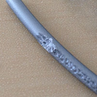
Filament grindingThe feeder screw has ground a groove into the filament |

ERROR - STOPPEDThe display shows a bed temperature sensor error |

Scratched top surfaceThe nozzle moves across the top surface and causes what looks like scratches. |

Protruding axesOne or more rods are sticking out from the side of the printer |

Random fill layers / Voids being closed upAn opening or a void in a model has "random" fill layers. Expected voids are completely filled in. |

First layer not sticking / Parts coming looseThe first layer of your print doesn't seem to want to stick or your parts come unstuck partway through the print. |

"Hairy" printsVery thin strands of plastic appear on the surface of the print. |

X or Y switch brokenThe display shows a message indicating that a switch is broken, typically during homing. |

Skipped layer/Bed dropYou find that a layer or more is missing in the middle of a print or you hear/see that the bed suddenly drops down too far. |

Misaligned axesThe rods going through the head are not perfectly square. |

Caked nozzlePlastic has leaked or extruded incorrectly and encased the nozzle in plastic. |
| Ultimaker 3 specific | ||

Front cover falling openThe front fan cover will not stay closed. |

ER18The printer stops and displays ER15 |
|
Warping 
Warping happens when the plastic cools and contracts. As the print cools down and shrinks slightly it starts to pull in on itself. Eventually the forces become so great that the print bends up from the platform. The best way to prevent this is with a heated build platform. By using a heated platform the plastic is kept just below the point where it goes solid, the so called glass transition temperature, and it therefore stays flat and connected to the platform. Although the heat from the platform is often enough it is also recommended to add a thin layer of glue to the platform to promote adhesion. Your printer will have come with a small stick of glue, spread a thin layer of glue onto the platform. Then, with a moistened rag or piece of paper, spread the glue out evenly onto the platform. As the bed heats the water will evaporate and leave a very nice thin and even layer of glue.
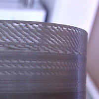
It is also important to make sure your bed is levelled as perfectly as you can. The plastic must be squished onto the platform so that it bonds properly. Besides preventing the print from coming loose or warping it also makes the bottom layer nice and shiny. You want the lines to be touching each other and all look identical to each other. Here's an example of what you're looking for:
 Notice how all the lines are uniform and touching. If the lines show signs of gaps your bed is levelled too low. If the lines are squished and messy it is likely your bed is too close.
A built in feature in cura called "brim" is another great way to help keep your print from warping. This feature puts what looks like the brim of a hat on the bottom layer of your print to help fight against the pulling forces of the cooling print. Since this brim is only a single layer thick it is very easy to remove once the print is complete.
The Ultimaker2 Go doesn't come with a heated bed so here you'll mostly have to rely on using the supplied blue painters tape and brim. Make sure you really press it onto the platform so that it doesn't easily lift off. You can also clean the surface of the tape with some alcohol to get rid of the waxy surface and any finger oils. This will make the print stick much harder. But since the bed on the Go is much smaller, warping is less of a problem.
Dealing with ABS
ABS is much more prone to warping than PLA and needs some extra care. Besides needing a higher bed temperature (remember to change the material setting on your machine to ABS) you also need to be more careful with cooling. If at all possible try to print without using the cooling fans at all. Ideally the printer should be enclosed to keep a constant temperature in the printing area. To promote bed adhesion you can make a slurry of ABS by dissolving a few bits of scrap ABS in a jar with Acetone Spread this slurry like a glue onto your build platform.
Leaning prints / Shifted layers 
Leaning:
A leaning print is usually caused by friction causing the print head to move a shorter distance than expected. Make sure that the short belts that connect the stepper motors to the axes do not rub up against the main body of the printer. Similarly make sure that the pulleys on the stepper motors that the belts ride over are not touching the side of the printer. If they are you must move the pulley closer to the stepper motor.

It is difficult to reach the set screws that secure the pulley to the motor and you will therefore have to remove the white cover plates that the motors sit behind. These panels are held in place with a single screw on the side of the machine if you have a slightly older printer. On the newer ones there are two screws, one on the back and one on the side. Remove the screw and then lift the covers off by tilting the cover slightly towards the front and them lifting them out. The only thing holding them in place is a small metal tab at the bottom of the cover that sticks down into the bottom of the printer.
On the Go there are no screws to remove. Instead the covers are held in place with small tabs that stick into the walls of the printer and into the bottom. These covers require a little bit of brute force to remove. Try pushing in the areas marked in the picture below and then pull the cover to the left. You'll likely have to wiggle the cover around a bit to get it loose. As you might imagine getting the covers back on can be a bit of a challenge but with some patience and finesse they'll snap back into place.

Now you will be able to reach the set screws of the pulleys. If you can't reach the screws easily simply move the head around so that they rotate into view. Undo the screw a turn or so and then push the pulley closer to the stepper motor. The pulley should be as close as possible without touching the stepper motor. Don't forget to re-tighten the screws when you are done and make sure they are very tight so that the pulleys cannot slip.
Shifted layers: 
If the printer suddenly shifts the layers it is most likely that one or more pulleys are not secured properly to the axis/axes. To confirm that this is the case you can use a black marker and put marks on the pulleys and a matching mark on the axes. After printing a test print and seeing a layer shift you can then inspect your marks and see which pulley(s) have moved. It is likely that the pulley(s) that need tightening are those connected to the short belts. Tighten the set screws that hold the pulleys in place very tightly, probably a bit tighter than you expect. The small allen key that came with your printer will flex as you tighten the screws. Don't forget to check the pullies that are attached directly to the motor shaft, you can read about those in the section above.
Try to move the head around manually with the power turned off. The head should move around quite easily and there should be similar resistance in both the X and Y direction. If the head is moving stiffly it is probably a good idea to give the rods a drop of light machine oil each (such as sewing machine oil).
Another cause for stiff movement can be misalignment of the rods so that they are not perfectly square. Check this by moving the head to the left/right side of the machine and checking that the distance between the sliding blocks and the pulleys are equal on both sides and then repeat for the front/back of the printer. If you notice that the axes aren't square you can fix this by loosening the set screws on the two pulleys of one rod so that the sliding block on that side can move without affecting the opposing block. Nudge the block the needed amount and then re-tighten the set screws.
It could also be that the part you are printing detached from the platform during the print. This should be fairly easy to see as the part will have shifted position from where it was originally.
Make sure that your glass plate is held firmly in place. If the clips aren't gripping the plate firmly enough it might shift slightly during the print. If they are too loose you can use a pair of pliers to gently squeeze the clips together.
In rare cases there could be an issue with end stops triggering unexpectedly due to cross talk between wires. Re-routing the cables can help with this. But again, this is a very rare occurrence.
Yet another, even more rare, cause can be overheating stepper drivers. A design change of the traces on the mainboard can lead to more current than expected to get to the stepper drivers. This causes the stepper motor to overheat which in turn kicks in the overheating protection in the driver. As the stepper overheats it shuts off for a fraction of a section to cool down and this is when the shift occurs.
You can check/fix this issue by lowering the amount of current for the x/Y steppers in the settings of the printer. Go to Maintenance -> Advanced -> Motion settings -> Current X-Y and set it to 1200mA and then attempt a new print.
"Pillowing" 
Pillowing show up as bumps in the top surface of a print and can either be open or closed. The most important thing here is to make sure that your cooling fans are going top speed when the printer is laying down the top layer. Without proper cooling the thin strands of plastic tend to curl up and stick up above the surface of the print and make it harder for subsequent layers to properly span over the gap. With good cooling the strands gradually grow over the gaps until it closes fully.
Besides cooling you also need to print a thick enough top surface so that the printer can properly close it. In general you should make sure that you are printing at least six top layers. Since the top and bottom thickness is set in mm you will have to do some basic math to make sure you're printing enough layers. If you are printing with a 0.1mm layer height you should make your top thickness at least 0.6mm.
In general you will need more top layers the thinner your layer height is. With very thin layers the thin strands of plastic are more likely to break before fully bridging over the gaps in the infill and providing a nice base for the following layer. You will therefore need to print more layers to make up for this. In other words very thin layers can be another cause of pillowing.
 This image shows two prints done with exactly the same settings, except for one, the bottom print did not have the cooling fans enabled.
Some users have also reported that the change in infill pattern between 24% and 25% (and up) makes a big difference. The difference between infill percentages at 24 or lower and 25 and higher is how cura lays down each layer. The infill is a crosshatch pattern made with diagonal intersecting lines. At lower densities both directions are laid down for each layer while at higher densities it is only laid down in one direction per layer. So, for layer X it will do lines from the lower left to the upper right. At layer X+1 it will do lines going from lower right to upper left.
Elephant's foot 
It's very common that the first couple of layers of a print is wider than you expected them to be. This is because you will generally want to make sure the first layer is nicely squished into the build platform so that it sticks properly. By doing this the plastic gets squished out into a thicker line than normal and thus the bottom of the print will bulge out a bit like an elephant's foot. You can decrease this effect by levelling your bed so that the nozzle is slightly further away from the bed and lowering the bed temperature a bit. It's hard to get rid of this effect entirely without sacrificing bottom layer quality and bed adhesion. It will be easier on small prints as they are less likely to warp and detach from the platform and you can therefore get away with not squishing the first layer as hard.
However, if you are the one who created the part there is a trick you can use to help get rid of this problem. Simply put a small chamfer on the bottom of your print. How big to make this chamfer depends on your print settings and what kind of edge you're looking to create. A good starting point is a 45 degree 0.5mm chamfer. You might be tempted to use a fillet instead of a chamfer for a rounder shape but these create a very severe overhang closest to the bed and rarely come out quite the way you expect. Feel free to experiment though.
Circles not round / Lines not touching 
A fairly common issue on the Ultimaker Original in particular (especially the kit versions) is that people try to print things with circles and the circles don't come out perfectly circular. At the same time infill lines are not touching the outside perimeter properly. You may also see that infill lines are grouped in pairs where two lines are touching followed by a gap and then another two lines touching. Both of these problems stem from the same issue and that is backlash caused by slack belts. Mainly it is the so called "short belts", which are the belts that are connected to the stepper motors, not being tight enough. Thankfully this is an easy fix.
 This image is a nice example of lines grouped in pairs. Notice that there are actually two lines very close together followed by a gap and then another two lines close together.
 To make sure the belts are tightened properly you need to loosen the four screws that hold the stepper motor in place. Don't remove the screws fully, just loosen them so that you can move the stepper motor up and down.
 Now press down firmly on the top of the motor so that the belt is nice and tight. While keeping pressure on the motor re-tighten the screws to lock the motor in place. Do this for both motors.
It's also a good idea to make sure that the rods are nicely lubricated. A single drop of light oil, such as sewing machine oil, on each rod is enough.
An additional step you might want to take while you're at it is to ensure that the set screws of the pulley on the motor is nice and tight, tighter than you might think should be enough.
Stringing 
The primary countermeasure for stringing is something called retraction. When you have retraction enabled the printer will "suck" the filament back a short distance before moving the print head over an open space. By sucking the filament in a bit it helps prevent plastic from dripping from the nozzle during the travel move.
So what you should do first is to make sure that retraction is actually enabled in cura. This setting is found on the "Basic" tab in the form of a checkbox when you are in the full settings mode (Expert -> Switch to full settings...). Make sure this box is checked. You can check if retractions will happen without printing by looking at the layer view in cura after slicing your object. You switch to layer view with the big button in the upper right corner of the window. The retractions are indicated by small blue lines that go from the print and straight up. It can sometimes be tricky to see these lines without zooming in and rotating the view around.
 As you can see it can be hard to spot these small lines unless you zoom in for a closer look. The other blue line indicates the travel move that the retraction is preparing for.
Another thing you can do to lessen the effect of stringing is to increase the travel speed. By default the travel speed is set to 150mm/s but you can increase this to 250mm/s. By increasing the travel speed you give the head less time to ooze plastic but you also help snap off any strands that form instead of dragging them along.
Temperature can also play a part. Experiment with a lower temperature.
 This image shows clearly how lowering the temperature has a very positive effect on the amount of stringing. As always when lowering temperature you must also make sure that you are printing slowly enough to prevent under extrusion. Note that the temperatures shown in this image is for PLA, for other materials you may not be able to go this low. Or conversely, you may be able to go even lower.
On the Ultimaker2 the speed and length of the retraction is set on the printer. The default values work well but feel free to play around. Increasing the retraction length for example can make up for sloppiness in the connection of the bowden tube to the print head.
Finally it should be noted that some filaments are simply prone to stringing and no matter what you do it might be all but impossible to completely eliminate them. Even different colours from the same manufacturer can differ in how much they string.
Ringing 
Ringing is what we call the small waves or shadows that usually appear around sharp corners on a print. It's often very apparent if you have text on your print as you will see what looks like shadows of the text. This happens when the print head makes a sudden direction change and the inertia of the head causes vibrations that show up in the print. To combat this there's a couple of things you can do. Simply slowing down your print speed will help lessen the effect. Decreasing the acceleration of the printer will make a big impact on the reduction of ringing without affecting print speed too heavily. You adjust this setting by going into the advanced settings on the printer itself Maintenance -> Advanced -> Motion settings. Try 3000 or 1500 and see how that affects your print.
There's also another defect that can look like ringing while it actually isn't. Something that can happen is that infill shows through to the outside layer. This can look similar to ringing. To get rid of this the solution is to print thicker outer walls to hide the infill. Try printing at least two outer shells which, with a standard nozzle, will equate to 0.8mm thick walls.
By default cura will print the infill before the walls, this makes it more likely that the infill will show through to the outer wall. The reason for printing in this order is because it helps with overhangs. But you can try reversing this order by going into Expert -> Expert settings and checking "Infill prints after perimeters"
Excessive temperature can also cause strange vertical lines in a print. Try lowering the temperature slightly and see if that helps.
Yet another thing to try is to rotate your part 45 degrees on the print bed. Some users have reported that this has gotten rid of vertical lines on the print.
Overhangs 
The reason overhangs come out uglier than a straight wall is simply because new layers are not properly supported by the preceding layer. Rather than fully resting and being anchored in place by the previous layer the new layers are partially printed into mid air and tend to sag down slightly or curl up. Sometimes these issues accumulate making each layer worse than the last. Curling around corners when using thin layers seems to be especially problematic. Dealing with overhangs is tricky, there are many variables that will affect how well or badly they will be printed. Temperature, print speed, amount of overhang, layer height, material, and cooling all play a part in how an overhang will print.
Like so many other things cooling plays one of the biggest roles in how well an overhang will print. Ensure that your cooling fans are going 100% when the overhang is being printed. If the object you're trying to print is small there's a chance that, due to the way the nozzle is positioned, the right fan never gets a chance to properly cool the print. A prime example of this is the right ear of the Ultimaker robot. A way around this is to print more than one object at the same time. By doing this the print head will move between the two objects and allow the layer of one object cool down while the same layer is being printed on the other copy. This also helps greatly when the layer currently being printed is very small. When printing very small details such as the antennas on the Ultimaker robot the print head will stay over the same spot for quite some time and transfer a lot of heat into the print which will deform the layer quite badly.
Another variable is layer height. Depending on your print, sometimes a thicker layer height will be helpful in improving the quality and sometimes a thinner layer is helpful. Thinner layers seem to create a more pronounced upward curling of the edges and especially around sharp corners. You'll simply have to experiment and see what works best in your situation.
Print speed will also affect your print quality. Slowing down will usually always result in an improvement.
Try to reduce the print temperature as much as possible without causing under extrusion. The slower you print the lower your print temperature can be. In addition to reducing the print temperature it can be worth lowering the print bed temperature, or even turning it off completely. This is especially important if the overhang is close to the bed.
If at all possible try to orient your object to minimize the amount of overhangs. Look at your model and imagine how the print head will have to move and then try to figure out how to rotate or angle it to make this easier. If you are the creator of the model do your best to avoid overhangs or reduce their severity. If it's possible to keep an overhang to 45 degrees instead of 30 that's a good thing as it will be much easier for the printer to handle. You might also consider changing your design to allow for a bridge rather than an overhang.
 The top object has an overhang that can be quite hard to get a nice clean surface on. The bottom object has replaced the overhang with a straight "roof" that can instead be bridged which can produce a cleaner result in some cases. Bridging is when the print head will print straight across a gap between two islands into mid air. This actually works better than you might think, especially if the jump is short.
There is a limit to how much of an overhang you can print while still preserving the quality you want and this is simply a limitation of the type of printer the Ultimaker is. Where this line is drawn depends on your own expectations, what plastic you are using, what the geometry of the overhang is, how well it can be cooled and many other factors.
Very visible lines on the bottom layer 
If the bottom layer of your print is showing very obvious print lines it's likely that your bed is simply levelled a little bit too far away from the nozzle. The closer to the nozzle the bed is on the first layer the harder the plastic will be squished into the bed and the lines will then blend together better. However, you can't go too closely as that will prevent the plastic from escaping from the nozzle properly. Pressure will build up and eventually the plastic will squirt out and create an ugly blob, or, it could cause the feeder to grind your filament which is something you don't want.
By default cura will print a 0.3mm thick first layer. You may want to try reducing this to 0.2mm or even 0.1mm to make the bottom layer even more of a mirror like surface. However, when you reduce the initial layer height you must be very precise in your bed levelling. A 0.3mm layer height is quite forgiving, a 0.1mm layer height is anything but.
Under extrusion 
What is it?
Under extrusion is simply that the printer can not supply the amount of plastic that is asked for. Symptoms of this is missing layers, very thin layers or layers that have random dots and holes in them. This problem is probably the trickiest to find the direct cause for as there are so many variables at play.
The printer will do its best to try and achieve the printing speeds that you are asking for. If this is beyond what the printer is capable of you will run into problems. If the printer is at the very edge of its capability the amount of plastic being extruded will be reduced but the print keeps going normally. When this happens your printed object might look ok at first glance but if you look closer you will see that walls are not properly fused and there are gaps between fill lines.
If you go beyond this in-the-middle stage the printer tries pushing harder and harder to extrude the material but eventually the pressure will be too high. Ideally when this happens the extruder motor will do what we call a skip back where the axis of the motor spins in the opposite direction for about a quarter turn to relieve pressure. This will not damage the printer, it's an intended behaviour to prevent the filament from being ground up by the feeder. You will hear when this happens as it will make a *tock* sound and if you look closely at the filament that is being extruded you will see a sudden reduction in volume.
If the skip back doesn't happen your filament will be ground down by the feeder and you will have to remove the filament and cut away the damaged part.
Do NOT increase flow to compensate
Let's get this out of the way from the start, this is a terrible idea and very counterproductive. Imagine trying to evacuate a building during a fire, hundreds of people are trying to squeeze through the single exit but only one at a time can exit. If only one person at a time can exit through the door, will it help if you add more people inside the building? This is essentially what increasing flow does in this situation. Increasing flow has its uses but preventing under extrusion is not one of them.
Respecting the limits of the printer
The simplest and probably the most common cause for under extrusion is simply that you are asking the printer to do more than it is capable of. We measure how fast a printer can print in volume of plastic per second: mm 3/s. In ideal conditions an Ultimaker2 is capable of printing about 10mm3/s. A more realistic limit is 8mm3/s but it should be noted that at these kinds of speeds the quality of the print will not be all that great and depending on the size of the object you are printing it might not even reach such a high speed due to the minimum layer cooling time slowing down the print speed.
To figure out how fast you're trying to print you simply multiply your nozzle diameter with the layer height and speed. So for example, if you're printing with 0.2mm layers at 60mm/s you would do: 0.4*0.2*60 = 4.8mm 3/s. This is a speed that a properly functioning Ultimaker2 should be able to handle without any problem.
Temperatures
The faster you print the less time the plastic has to heat up to proper printing temperature before being forced out through the nozzle. Cooler plastic is more viscous and requires higher pressures to push it through the nozzle and eventually the pressures will simply become too high and under extrusion happens. So, can you increase the temperature to work around this issue? Yes, you can, but within reason. Setting a temperature above 240-245C for PLA is starting to get into bad territory as the plastic will start to change properties if left in the nozzle for too long and can cause clogs. If you have to raise the temperature this high while still printing at normal speeds there is something else going on. You will also likely see degrading print quality at these temperatures such as increased stringing and worse overhangs.
Grinding 
If you experience under extrusion, find that the filament has been eaten away by the feeder (grinding) and you don't have a clogged nozzle you likely need to adjust the tension of the feeder. On top of the feeder, to the right of where the bowden tube enters there's a small hole with a tension setting screw inside of. On the front and the side of the feeder there are two white dials that indicate the feeder pressure.
Ultimaker2: In March of 2014 the spring inside the feeder was changed and the proper setting will therefore differ depending on when you received your printer. For machines from before March of 2014 the indicator should be at the middle and for machines after this date the indicator should be at the top.
Ultimaker2+: The default setting for the Ultimaker2+ is in the middle.
You want to adjust the tension so that the feeder never grinds the filament but rather skips back when the pressure becomes too high. Try increasing the pressure first (moving the indicator further down). When properly adjusted the motor will skip back to protect the filament from grinding so that the feeder can always get a good grip (and prevent damage).
Note that the new feeder on the Ultimaker2+ will not skip like the older feeder of the Ultimaker2 as it has changed to a geared and stronger design.
Tightly coiled filament
Towards the end of a roll of filament the coils are usually small and tight. When going through the bowden tube the filament will experience higher friction than if the filament was nice and straight. If you're printing at the limit of what the printer can achieve this additional friction can be enough to push it over the edge.
Tangled filament
This might seem obvious but make sure that your filament can unspool unhindered. Check that the filament isn't overlapping on the spool for example. It is not uncommon to have the filament loop under itself when you remove it from the printer for storage and it can be hard to see.
Clogged nozzle
Due to the tiny exit hole on the nozzle it doesn't take much for the exit to become fully or partially blocked. Blockages can have a wide variety of causes such as unexpected contaminants in the filament (with good quality filament this is very unlikely), excessive dust or pet hair on the filament, burnt filament or residue of filament with a higher melting point than what you're currently using.
If you've recently switched from printing with a material that requires fairly high extrusion temperatures such as ABS to a plastic with a lower extrusion temperature like PLA it is important to get rid of all the ABS in your nozzle. Often you can get rid of the old plastic by simply manually extruding the new material at the higher temperature required for the old filament. When using a higher temperature than you would normally use it is important to not let the plastic sit in the nozzle for too long. Doing so may cause the plastic to burn and block the nozzle.
If there is something physically blocking the nozzle such as dust build-up or something along those lines, a very good method to start with is what's referred to as the "Atomic" or "cold pull" method. Click here for instructions
Usually performing this operation a few times will take care of the problem. If it does not you can use a very thin wire to poke into the nozzle to help dislodge whatever it is that is causing the blockage. A popular tool for this is acupuncture needles. These can be bought cheaply on Ebay for example or you can contact us and we can supply them for you. Any sufficiently thin (the opening of the nozzle is 0.4mm in diameter) and stiff wire can be used however, just be very careful not to damage your nozzle. After dislodging the blockage perform the Atomic method again to extract it.
As a last resort you can remove the nozzle completely and try to burn out any residue in the nozzle with a propane torch. This is a fairly lengthy procedure on the Ultimaker2 as it requires disassembly of the print head and it is rarely needed. The Ultimaker2+ however has an Olsson block which makes it possible to unscrew just the nozzle making it easier to either replace the nozzle completely or making it easier to clean out.
Combing
Modern slicer software uses a method called combing to prevent stringing. When the print head needs to move from one part of a print to another and there is a void between the two locations combing causes the head to move inside the perimeter of the part instead of crossing across voids. This makes it so that any dribbling from the nozzle gets deposited inside the part where it is not seen. A side effect of this can be that the reservoir in the tip empties out ever so slightly and when it starts to print again it takes a moment for the reservoir to fill back up. As the reservoir is filling up little to no plastic is actually extruded. It should be noted that usually this isn't an issue for shorter travel moves. It is when the head needs to make a long trip that it can cause issues.
You can switch off this behaviour in the expert settings: Expert -> Open Expert Settings... If this option is greyed out you need to first switch cura to the full settings mode: Expert -> Switch to full settings Once you have the expert settings open the combing option is located under the "Retraction" settings in the top left. If you uncheck the "Combing" checkbox cura will perform a retraction and then move in a straight line when it needs to move the head from one point to another.
It is up to you to decide which behaviour you prefer. If combing isn't causing problems for you then you may prefer leaving it enabled as it saves a little bit of time. Whether or not combing will cause a long travel move leading to under extrusion issues depends on the geometry of the model you're trying to print. There isn't a definitive correct choice here.
Deformed teflon insulator
Before reaching the hot zone of the nozzle the filament will pass through a white insulator piece. If the print head has seen excessive temperature in combination with a very tightly assembled print head it could happen that the exit of this insulating piece gets slightly deformed. If the exit diameter has deformed it could cause unnecessary friction making it more difficult for the feeder to extrude properly. To find out if this is the case you have to disassemble the print head. Once taken apart you can have a close look at the insulator paying particular attention to the exit hole. Try feeding a straightened piece of filament through it, there should be no resistance. If a lip has formed at the exit causing friction you can try to very carefully use a drill bit to remove this lip. However it is important that you remove only the lip and nothing more. The insulator must form a very tight seal against the hotend so that no plastic can leak out.
If you are not comfortable performing this operation or feel you need a replacement part please get in contact with your reseller or Ultimaker.
Ultimaker2+: Please note that because the Ultimaker2+ no longer uses a spring but instead uses a solid spacer, it is critical that the distance between the two metal plates is correct. A small tool will be made available for this eventually.
Filament diameter
High quality filaments have very high tolerances and are produced with a diameter around 2.85mm. This can be misleading as they are usually sold as "3mm". This is not because they are trying to trick you but to make sure the filament works properly in the printer. If you buy cheap filament make sure that the diameter does not exceed 3mm. Also note that some filaments may be slightly oval so measure twice, rotate your callipers 90 degrees for the second measurement. If your filament exceeds 3mm there is a good chance that it will jam in the printer as it will simply be too thick to pass through the print head. And even if it does pass through it may cause excessive friction which in turn leads to under extrusion. Really your best option is to not use it to avoid head aches.
Besides making sure that your filament isn't too thick it is also important that the printer/slicer software knows the diameter of your filament. On an Ultimaker Original this is a setting in cura (or any other slicer you are using), for the Ultimaker2 this is set on the machine itself. Why is it important you ask? it is important as this measurement is used by the slicer/printer to determine how much filament to feed to produce the line width you want. If your settings say your filament is 2.9mm in diameter but your filament is actually 2.7mm the printer will be feeding through slightly less material than it actually needs. This will not create a dramatic difference but it can for example be seen as tiny spaces between the lines in a top surface. It can be the difference between a water tight print and a print that leaks.
Feeder wheel
The material is fed into the print head by a small knurled wheel in the feeder at the back of the printer. The knurled wheel is a sort of sleeve that is attached to the motor shaft of the feeder motor. it is important that this sleeve isn't able to slip. To make sure it isn't you can put a small mark on the shaft and a matching one on the sleeve. After printing something, inspect the marks and make sure they haven't moved in relation to each other. If they have you will have to tighten the small set screw that holds the wheel in place.
On newer Ultimaker2 printers this is less likely to happen as the shaft is no longer round. A small cutout helps keep the wheel in place. But it's still something to check, just in case.
For the Ultimaker2+ this is not relevant.
Nozzle too close to the glass
This is mostly an issue that can show up on the UM2+ with its stronger feeder. If you level the nozzle too close to the bed you will essentially block the plastic from coming out. With the older feeder design this would cause the feeder to skip and thus save the filament. With the new, stronger feeder there's a chance that it will just keep pushing and start to grind down the filament.
Walls not touching 
First of all you have to determine if the walls are not touching at all or if they are touching in some parts only. Using a cylinder as an example it is common that there will be two "sides" touching and two that do not.
Partially touching
This is very likely caused by the short belts not being tight enough. Please see this section which deals with this issue.
 Notice how some parts of the infill lines are touching the perimeter lines while others do not. You will usually find that if you imagine drawing a big X over the print you will notice that the bottom left and top right patterns match and similarly the top left and bottom right match.
Not touching at all
If the walls are not touching each other at all it is an extrusion issue. cura is asking your printer to create a series of 0.4mm lines and is spacing them so that they fuse together. However, if your printer is under extruding slightly the lines will be marginally thinner and they no longer fuse together properly. The solution could be as simple as reducing your print speed slightly or increasing your temperature a few degrees. Under extrusion is an issue with many causes and you can read more about it here.
Another possible cause
There is however something else that might be happening and it is a slicer issue that relates to wall thickness and the size of your nozzle. We call it the "thin wall problem". The standard nozzle on an Ultimaker is 0.4mm in diameter so that is the width that cura has to work with to produce your print. Now, say that you have a wall that is 1mm thick, how will cura handle this? It creates two perimeter walls that are 0.4mm each. This leaves a 0.2mm gap between the walls and since the nozzle is twice as big cura cannot fit the nozzle between the walls to fill the void. It should be said that cura is pretty good at dealing with this and will try some tricks to get around this issue but when it fails this void between walls is what you will end up with.
To get around this particular problem you should always try to design thin walls to be multiples of your nozzle size. If that's not possible you can cheat a bit by changing your nozzle size setting in cura to something slightly smaller and try again. This will cause cura to slightly under extrude to create a thinner line. You can also increase the size to do the opposite. However, it's very important that you then watch your print speeds as the volume you're trying to extrude will go up drastically. It is important that you match your wall thickness settings to match your new nozzle setting, you want your wall thickness to be a multiple of your nozzle diameter. If you set your nozzle diameter to 0.3mm you want your wall settings to be 0.3mm, 0.6mm, 0.9mm etc.
It is also worth experimenting with the wall thickness setting and infill percentage. If you're not getting the result you want with 0.8mm walls you can try 0.4mm or 1.2mm for example. Sometimes having a thinner outer wall helps fill in these thin walls and vice versa. You don't have to print it out to check, instead use the built in layer view in cura to check your changes. The layer view is found by clicking the big button in the top right of the window.
 This image shows a classic case of the thin wall problem.
Lower wall cave in 
Excessive bed heat is the culprit in this case. As the plastic is extruded it behaves similarly to a rubber band. Normally this effect is held back by the previous layers in a print. As a fresh line of plastic is laid down it bonds to the previous layer and is held in place until it fully cools down below the glass transition temperature (where the plastic becomes solid). With a very hot bed the plastic is held above this temperature and is still malleable. As new layers of plastic is put down on top of this semi solid mass of plastic the shrinking forces causes the object to shrink. This continues until the print reaches a height where the heat from the bed no longer keeps the object above this temperature and each layer becomes solid before the next layer is put down thus keeping everything in place.
For PLA you will want to keep your bed temperature at around 50-60C which is a nice temperature to keep bed adhesion while not being too hot. By default the bed temperature is set to 75C which is definitely too much for PLA. There is an exception to this however. If you're printing objects with a very large foot print taking up most of the bed it might be necessary to use a higher bed temperature to make sure the corners do not lift.
In addition to lowering your bed temperature you want your fans to come on early to help cool down the layers as fast as possible. You can change this in the expert settings of cura: Expert -> Open Expert Settings... In the window that opens you will find a section dedicated to cooling. Try setting Fan full on at height to 1mm so that the fans come on nice and early.
If you are printing a very small part these steps might not be enough. The layers might simply not have enough time to cool properly before the next layer is put down. To help with this you can print two copies of your object at once so that the print head will alternate between the two copies giving each more time to cool.
Grinding
Grinding happens when the motor tries to push the filament through the nozzle but for whatever reason it starts to slip on the filament and instead grinds the plastic down. The more it grinds the filament the less grip it is able to get and very soon it will not be able to move the filament neither in nor out. This is more common on the Ultimaker Original but it can also happen on the Ultimaker2. To help prevent this problem on the UM2 the feeder motor current is deliberately limited so that the motor will skip back before starting to grind the filament down. When this happens you will hear a *tock* sound and the feeder wheel will spin in reverse for about a quarter turn.
What prevents the feeder from moving the material forward properly can differ and what follows is a few things you will want to check.
Tangled filament
This might seem obvious but make sure that your filament can unspool unhindered. Check that the filament isn't overlapping on the spool for example. It is not uncommon to have the filament loop under itself when you remove it from the printer for storage and it can be hard to see.
Feeder pressure
The amount of pressure that the feeder puts on your filament is adjustable via a small hidden screw accessed at the top of the feeder. To the right of where the bowden tube enters the feeder there is a small hole into which you can insert a hex driver to adjust the tension. The current setting can be seen on the little white dial right below this hole. When the dial is in the upper position the pressure is low and vice versa.
Ultimaker2:In March of 2014 the spring inside the feeder was changed and the proper setting will therefore differ depending on when you received your printer. For machines from before March of 2014 the indicator should be at the middle and for machines after this date the indicator should be at the top.
Ultimaker2+:The default setting for the Ultimaker2+ is in the middle.
You want to adjust the tension so that the feeder never grinds the filament but rather skips back when the pressure becomes too high. Try increasing the pressure first (moving the indicator further down). When properly adjusted the motor will skip back to protect the filament from grinding so that the feeder can always get a good grip (and prevent damage).
Note that the new feeder on the Ultimaker2+ will not skip like the older feeder of the Ultimaker2 as it has changed to a geared and stronger design.
Update firmware for your UM2
An unfortunate bug in the firmware of the UM2 can cause grinding to happen at the start of a print due to excessive priming speed. Please make sure that you use the firmware that shipped with cura 14.07 or later. You can download the latest version of cura here: Software download
Check the "third" fan
The print head of the UM2 has three fans, the two print cooling fans on the left and right side and what we call the third fan that is located at the back of the head. it is very important that this fan is running whenever the hotend is heated up. Depending on how old your printer is the fan should turn on as soon as the printer is powered on or as soon as the print head reaches a temperature of more than 40C. The function of this fan is to cool the zone of the print head where the plastic goes from liquid to solid, it is important that there is a sharp distinction between these two zones and that heat doesn't travel upwards in the system. If the third fan is not running heat will travel up in the system and soften the filament much higher up than intended. The softened filament will then expand and cause a clog that will make it impossible to print until it is removed.
If you find that the fan is not running you should check that the fan is properly connected. The connector is hidden under the black wire mesh guard and you will need to move it out of the way. It may be that the mesh has heat shrink tubing that need to be removed before you are able to move the mesh out of the way. Use a small scissor or pliers and carefully cut the tubing away being careful not to cut any cables. The heat shrink tubing is cosmetic and removing it will not impact performance in any way.
Trace the wire from the fan to it's connector. The fan should connect to an orange and blue wire. Tug gently on the connection to make sure it is solidly connected and check that it hasn't somehow been connected in reverse.
 This image shows a proper connection. Notice how the little "hooks" secure the two connectors together. Also take note of the colour order of the wires. There have been a couple of cases (in other words, rare) that the wires have been assembled in the wrong order.
 In this case one of the internal metallic connectors have slipped out of the housing. This may cause intermittent behaviour in which the fan turns on only when the print head is in certain positions. It is important that you fix this and you will start by first disconnecting the fan and then gently pulling the loose wire out completely.
 Inspect the connector and see that the little retaining barb on the top is bent outward.
 Then re-insert the wire into the housing all the way until you hear a faint click as the little barb snaps into place. It can be difficult to hear this so take a look and check that the wire is indeed fully inserted. Give the wires a little tug to check that they are held securely in place. Finally re-connect the fan.
Clean the knurled sleeve
It is possible that plastic is clogging up the knurled surface that is supposed to grip into the filament. Usually blowing sharply at the surface will get rid of the debris but using a small brush, like a toothbrush, is helpful to make sure the surface is nice and clean. It is especially important to clean the sleeve after you have had a grind as it is then very likely it will be full of plastic shavings.
Excessive stepper axis heat
This one is a bit more obscure but we've seen a couple of cases where the shaft of the feeder motor gets so hot that it heats up the filament to the point where it gets slightly soft. This is mostly an issue with PLA as it has a lower glass transition temperature than for example XT or ABS. Due to the extra heat the filament will start to deform and flatten out which in turn leads to extrusion problems. Prints with a lot of retractions are of course affected more than a print where the filament is steadily feeding into the printer.
This seems to be more of a problem when the printer is located in a place with already very high ambient temperatures. If you suspect this is happening on your printer you can try the following to see if it helps. Remove the white metal cover that hides the stepper motor and then direct a fan at the stepper to cool it down. You could also possibly try to cool the area down from behind the printer but it's harder since there is so little of the shaft exposed.
Also see this section of the guide.
ERROR - STOPPED Temp sensor bed 
The firmware has detected that the temperature sensor of the bed is reporting incorrect values. Without proper feedback from the sensor the firmware can't control the bed heat so to protect the printer and for safety reasons the firmware will prevent you from using the printer until this problem is fixed.
Important warranty note: before you perform any of these steps you must contact the Ultimaker support team first
Most likely the error is caused by a connection issue. This can happen in a few locations:
- Where the wires connect to the PCB underneath the printer
- At the bed connector
- The wires themselves may be damaged
The easiest thing to check is the connector on the heated bed so let's start there. Follow the cables that connect to the bed. There will be four wires two thick ones and two thinner ones. The sensor wires are the thinner ones. Try tugging gently on these wires and make sure that they are securely fastened. If they are not properly secured you will need to remove the heated bed so that you can access the connector and re-seat the wires properly.

If any of the wires are loose you will need to remove the heated bed so that you can reach the connector. Start by removing the strain relief that hold the wires to the bed. The bed is held in place by three screws that connect to the three thumbscrews on the underside of the build plate. Unscrew all three screws completely and lift the bed off. Be ready to catch the thumbscrews as they are not held in place. You will now have full access to the bed connector and it should be straight forward to re-insert the wires and tighten them into place. While you have access you should also inspect the solder joints that hold the connector to the heated bed. Check for cracks or other damage. If you find a bad connection you will need to re-flow the solder joints. If you are not comfortable doing this yourself then maybe you know someone who has experience with a soldering iron. If not, get in contact with us and we'll make sure to get it fixed for you.
Now check that the sensor is properly plugged into the PCB at the bottom of your printer. To access the PCB you will need to remove the protective metal cover. There are two metal covers, the one you want to remove is the bigger one. The cover is held in place by a couple of screws that you unscrew from inside the print area of the printer. Start by lifting the bed out of the way by grabbing the bed with both hands as close to the back of the printer as possible and lifting it straight up. Lay the machine on its side and remove the two screws and finally remove the cover, it might take a bit of wiggling back and forth to dislodge the cover. The sensor cable is white and brown and should be connected to "Temp3" on the PCB:

Unscrew these two screws to release the electronics cover.
 Check that the white and brown cable is inserted into "Temp3".
Scratches 
As the print head is completing a top layer travel moves can cause ugly lines to appear. This can be caused by a couple of things. Either the head is making an actual scratch on the surface or you are seeing slight oozing of plastic during the travel move.
You can try to enable the "z-hop" feature in cura which will find in the expert settings under the retraction heading: Expert -> Open expert settings... This feature will make the printer lift the nozzle a tiny amount just before making a travel move and then move back down once it arrives at the destination. In combination with this you can increase the speed at which the printer executes travel moves. You can increase the default 150mm/s to 250mm/s without problems. The faster move will reduce the amount of time the nozzle can ooze out plastic. Also consider lowering your temperature to further reduce oozing.
To reduce oozing even more you can set the Minimum travel distance to 1 and set Minimum extrusion to 0. This will force cura to always retract before performing a travel move. This may add a bit of printing time as a retraction doesn't happen instantly.
A side effect of the z-hop feature is that it can leave behind a tiny little blob. However, a small blob is far less visible and easier to remove than a scratch.
This effect is more prone to happen on surfaces which are broken up by holes since the head needs to move around more. "Dreamworker" on the Ultimaker forums came up with a clever workaround to reduce the complexity of the top surface. By adding a thin solid layer on top of the object he was able to reduce the travel moves significantly. The thin layer of plastic was then cut to reveal the holes again.
A little bit more information and another option to reduce this effect can be found here: Getting better prints guide
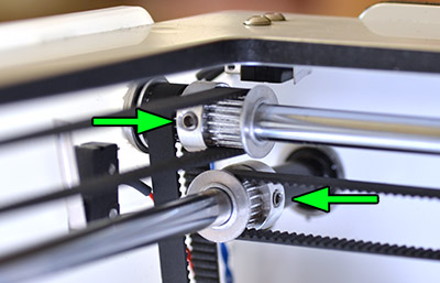
Protruding axes / Rods sticking out 
This can happen if a set screw on one of the pulleys has come loose and it's easy to fix. The image at the top of the page shows a fairly extreme case, sometimes it only sticks out a mm or two and can be hard to spot. Usually a small deviation like that will not affect performance or quality but you might experience a strange knocking sound that is hard to locate. If the rod isn't held tightly in place it will move back and forth with the print head and will make a knocking sound as the spacer is banging up against the side of the machine.
 Start by loosening the set screw on the offending pulley fully to make it easier to move. Next push the metal rod back into the correct position. In the image the arrow is pointing to a black spacer, push the loosened pulley towards this spacer until it is pushing up tightly against the bearing. Finally re-tighten the set screw very tightly so that it cannot slip again.
Random fill layers / Voids being closed up 
The example image shows a part where the opening at the top has a single fill layer covering it. You might also find that voids inside your model are either completely filled or randomly filled by infill layers. This happens due to errors in the model file that confuses the slicer. You can often spot these errors by viewing the model in "X-Ray" mode which you can activate by clicking the large button in the top right of the model window in cura. Any areas showing up as red are problem areas that will potentially cause issues.
 This model shows a whole heap of errors. You do not want any red areas at all when viewing your model in X-Ray mode.
cura has a number of options grouped under the "Fix horrible" heading in the expert settings. Knowing which option to enable/disable or which combinations will work is simply down to trial and error. Switch to "Layers" mode with the same button as before and inspect the trouble areas as you try different combinations. It should be noted that enabling these options for a model that isn't faulty can actually make the model slice incorrectly (see the image below).
A better option might be to repair the model so that the problem doesn't present in the first place. Netfabb offers a free cloud based service that will attempt to heal models for you. Since it's free it's well worth giving it a shot. You can find the service here.
 This image clearly shows how the sliced file does not represent what you would expect. Where the holes should be there is now infill. What's interesting is that the file is actually perfectly fine but by accident the "Combine everything (Type-B)" checkbox under "Fix horrible" was checked. With that option unchecked the file sliced without issues.
First layer not sticking / Parts coming loose 
By far the most common issue here is simply that you haven't properly levelled your print bed. It is very important that the bed is perfectly level in relation to the movement of the print head and that the starting distance from the nozzle is as close to perfect as possible. If the first layer starts just slightly too high the plastic will not be squished into the print bed properly and will therefore not stick and stay in place. You might also find that the parts are detaching before the print is completed.
When you first started your machine you were guided through a bed levelling wizard, you can re-start this at any time. Start the wizard with Maintenance -> Buildplate. Internally the firmware expects the bed to be 0.1mm from the nozzle tip at the end of the wizard. It just so happens that a sheet of standard 80gr printer paper is usually of this thickness and can be used as a crude feeler gauge. You want the paper to be able to slide in under the nozzle but you should feel a bit of drag/scraping on the paper. As you get more confident you might find that it's easier to simply look along the glass and visually set the correct height. You want the nozzle to be very close to touching its own reflection without actually touching.
You might have to re-do this procedure a couple of times to get it right, it'll get easier with time and luckily the Ultimaker2 build platform is very stable and rarely needs to be re-calibrated.
You can also adjust the levelling on the fly as the printer is laying down the first layer. Simply use the thumbscrews underneath the platform.
You'll find an image showing an example of a good first layer in the warping section.
It is also very important that your print bed is clean (glue is an exception of course) and free from oils from your fingers. If you've touched your print bed a lot the oils from your fingers can prevent or make it harder for the plastic to stick properly. To promote stickiness your machine was delivered with a stick of glue. Using glue is optional but tends to help quite a bit. Don't go crazy with the glue though, more is not better. Clean your glass plate and then spread a bit of the glue onto it. With a damp piece of paper or cloth spread the glue out over the bed and let it dry (starting a print that uses the heated bed will make it dry quickly). After the water evaporates you will be left with a very thin layer of glue.
If you're printing on a cold bed with blue painters tape, like on the Ultimaker Original, it is very helpful to wipe the tape down with some alcohol. The tape is covered with a waxy substance that can make it harder for the parts to stick. This isn't always needed but it's something to keep in mind.
"Hairy" print 
This is a tricky problem without a clear solution at the moment. This problem should not be confused with stringing which is a different issue. This problem is similar to stringing in appearance but the strands of plastic are very very thin and they seem to be able to appear even if there are no travel moves crossing over voids.
It seems to be fairly material dependent so consider trying a different roll of plastic and see if that helps.
Also make sure that your nozzle is clean so that small amounts of plastic isn't being deposited randomly during the print.
Thankfully the little hairs are quite easy to remove. Rubbing them off with your fingers work quite well. Another way, if you're a bit lazy, is to hit the print with the flame from a "jet" lighter very briefly. This will burn away the strands pretty cleanly. Don't use a regular lighter or a candle as it will likely leave ugly marks on it.
If you've figured out the cause and fix for this we would love to hear from you, find the contact e-mail at the top of this page.
X or Y switch broken 
This error will typically show up when the head is "homing", meaning when the printer is trying to find the origin point for the head. This happens whenever you start a print. The head will move towards the back left corner of your printer and wait for the head to trigger the little limit switches that are located in this corner. If this doesn't happen the way the firmware is expecting, it will throw this error.
If the printer is making a terrible grinding noise just before this error shows up it might simply be that the head isn't properly triggering the end switches. The switches are located in the top left of the printer and should make a faint clicking sound when you move the print head towards the corner. If you turn off your printer you can easily move the head by hand to check this. If either of the switches don't make a sound before you physically can't move your head any further that indicates that something is wrong. Likely you can fix this by simply using a pair of pliers and gently bending the little metal tab of the switch so that it triggers earlier.
Also check that the fan shroud isn't hitting the left wall of the printer and preventing the head from moving all the way to the left. If it does, use some gentle force and bend the fan shroud downwards a bit so that it clears the wall.
A common cause for this error is a loose pulley. If you've recently received your printer or if you've transported it there's a small chance that vibrations have caused the little set screws to become loosened. In this case the most likely suspects are the pulleys that the short belts run over so start by checking the set screws of those pulleys. The set screw of the pulley on the stepper motor shaft can be quite tricky to get to depending on what tools you have so you might have to remove the motor in order to get to it. This isn't difficult but can be a bit scary if you've never done it before.
The first step is to remove the white cover plates that hide the motors. These are attached with two screws from the outside of the printer. Remove those and then lift the cover out. Next you will loosen the four screws that hold the motor in place and you will now be able to get to the little set screw. When re-attaching the motor, make sure that the short belt is tight and that you don't pinch any wires. This section of the guide shows you the screws and how to tighten the belts.
Speaking of pinched wires. Now that you have the covers off it's a good opportunity to check that the wires of the limit switches haven't been pinched or damaged. The switches are located in the top left corner of the printer. Simply follow the wires and check that they look ok.
If you've checked all the set screws and they are all tight, the next thing to check is the connections. To do this you will have to remove the cover on the electronics board underneath your printer. Disconnect power and then unscrew these two screws which hold the cover in place:
Once you've removed the cover you will check the wires going to the spots marked "X-stop" and "Y-stop". Make sure the cables are plugged in properly. If the wires are plugged in fully and it still doesn't work (you can test this with the printer lying on its side via the menu entry Maintenance -> Advanced -> Home head) and you have access to a multimeter you can check that the switch is functioning properly. Set your multimeter to continuity check, disconnect the wire, probe the tiny metal tabs which you can see through the holes in the case of the plug and press the little end switch. You'll likely need someone to help you here as it's a job for three hands.
If none of the steps above find anything wrong the next step might be to see if there's something wrong with the controller board. It's best that you contact the place you bought your printer from if this is the case so that they can further help you.
Skipped layer/Bed drop 
Several things can be at play here as different issues can show very similar error in the print - a missing layer.
Underextrusion
One common cause can be temporary underextrusion. Extrusion is prohibited for some reason, such as a tangle on the spool, for a few layers and the printer then continues as normal. See the underextrusion section for more information about this.
Lubrication of z-screw
Another cause can be a lack of lubrication on the z-axis threaded rod. Your printer came with a little bag of accessories, in there you will find a small sachet of green grease that is meant for the threaded rod. Spread out some grease on the rod and move the bed up and down to spread it out thoroughly. It's important that you grab the bed towards the back of the machine while doing this so that you don't risk bending the bed. While doing this it's a good idea to also inspect the screw to see that there isn't some sort of debris causing issues (such as a small piece of PLA for example).
Misalignment of bearings
Next up is some sort of excessive friction causing the bed to bind up until the motor is able to break it free causing a sudden, and too large, drop of the bed. Turn the machine off and manually move the bed up and down to see if you can feel if there is a certain spot that seems to have much higher friction than the rest of the movement.
If you feel that the bed is binding somewhere it could be that the rods are not perfectly aligned with the linear bearings. A classic example of this is a drawer that is pushed in slightly askew, it will bind in place. To remedy this you will have to first remove the cover plate that hides the linear bearings. Two screws on the underside of the bed hold it in place. Once you have removed the screws you can simply lift it to free it. Use a piece of tape to hold it at the top of the printer, out of the way.
Now comes the tedious part. In order to re-align the bearing you need to loosen the four screws that hold each bearing in place. Loosen all but one of the 8 screws. As soon as you've done this it will be hard to move the bed as it will very easily bind in place, patience is key here. Wiggle the bed and move it up and down a bit so that the bearing can self align, tighten one of the screws and then wiggle the platform again and then tighten the two remaining screws. Repeat the same process for the other bearing. Try moving the bed fully up and down and see if you got any improvement. You may have to repeat this once or twice as it can be tricky to get things in just the correct location.
Too much oil
One user reported that he had oiled the two thick rods of the z-stage and this caused issues. Once the oil had been cleaned off again, the problem went away. Worth a try.
Overheating due to excessive current
Due to a slight design flaw of a revision of the controller board it's possible that some printers will have a problem where excess current to the stepper drivers cause issues. What happens is that the stepper drivers overheat, the protection circuitry of the chip kicks in and shuts the driver down for a brief moment, during this moment there's a chance that the bed moves down unpredictably.
Thankfully this is usually easily fixed by simply lowering the current for the stepper motors. This is done on the printer via Maintenance -> Advanced -> Motion settings -> Current Z. The default value is 1300mA, try lowering this to 1200mA.
Faulty rods or bearing
Unfortunately it is also possible that something is wrong with either the rods or linear bearings of the z-stage. If you've tried all the other solutions listed above it might be time to contact your re-seller or Ultimaker themselves to get replacements for these.
Spool holder interference with bed
Check to make sure that the parts of the spool holder that sticks into the machine isn't hitting any part of the z-stage such as the "cap" that goes over the linear bearings or the bed itself. It's possible that you could see some scratch marks on the holder itself.
The easiest way to get around this would be to simply take a file and remove a mm or two from the spool holder tabs. Another, more involved, way to possibly solve it is to move the bed forward. This is done by removing the cover over the linear bearings, loosening the screws on the bearings and then pulling the bed forward. The tricky part here is to get the bearings perfectly aligned with the rods again afterwards. It's very easy for them to start binding if they're not. Using a file will take a minute or two at most so it's a much much less involved process.
Misaligned axes 
If you find that your prints looked skewed this could be the issue. You might find that your prints look like this, where things seem to fit when you line the prints up in the same direction they were printed, but as you rotate them around you find that they no longer fit at all.

Another symptom can be excessive friction when you try to move the head around.
You might also notice it just by looking at the printer from the top and notice that something doesn't look quite right. Regardless, the fix is quite simple. There's a couple of methods you can use, the first one we describe is the one we usually use. You will start by turning off the machine so that you can move the head around freely by hand and then moving the head to the front center of the machine, as far towards you as it can go.
 Now take a look where the black sliding blocks meet up with the pulleys at the corner. Check the distance between the pulley and the sliding block and compare it to the distance on the opposite side.
 You want this distance to be as close to identical on both sides as you can get it. If you find that there's a difference you need to adjust it. To be able to do so you have to loosen the set screws of the two pulleys that control the movement of the sliding block. In this example we're going to move the left hand side block and to do so we need to loosen these two pulleys.
 Doing so will allow us to move this sliding block without affecting it's brother/sister on the other side. It's rare that you are lucky enough to be able to reach both screws without having to move the head so make a mental note of how much you need to move the block and then move the head so that you can reach the screws. After you are done adjusting make sure you tighten the screws back up, and do it very tightly.
Repeat the same procedure but this time put the head in the middle left (or right if that's more convenient). You may have to repeat this procedure a couple of times to get things perfect (or close to it).
Another option to visually measuring the distance is to use a tool such as this: https://www.youmagine.com/designs/adjustable-axis-alignment-tool . The "downside" to using these is that you often run into the problem mentioned above where you can't find a spot where you can reach both set screws.
Caked nozzle
There's a couple of different ways this can happen. If you have an Olsson block installed on your printer (standard on the UM2+) it could be that the nozzle hasn't been installed correctly and plastic can then leak out between the threads.
To make sure this doesn't happen it's important to make sure that the block is heated up to printing temperature when you change nozzles. If you don't heat up the block, leftover plastic in the threads and on the mating surfaces of the block and nozzle can prevent them from making proper contact. By heating up the block you cause the plastic to be runny and it will be pushed out of the way as you tighten.
It's also a good idea to print out this torque wrench so that you don't over-tighten the nozzle.
The other cause can be that the print comes loose from the platform or that it never stuck in the first place. If the print detaches from the platform it can stick to the nozzle and prevent plastic from flowing correctly. This causes it to curl up and flow upwards along the side of the nozzle and block.
Preventing this is a matter of correct bed levelling and making sure that the part has good adhesion to the platform during the print. This can include using brim, cleaning the bed and/or adding glue and making sure that the platform has the correct temperature for the material you're using.
Removing the block of plastic isn't difficult but can require some patience and time. Let's say that the plastic in question is PLA, start by heating up the print head to ~100C and let the heat transfer into the plastic for a couple of minutes to soften it. If you're lucky you will now be able to remove the block of plastic in one go. At the very least you should be able to get rid of the worst of it. If the plastic wont budge, start increasing the temperature in increments until it starts to give in.
If the plastic has spread around the two wires coming out of the heater block you should be careful not to pull on the wires too hard as you might break them. It's primarily the smaller of the two (the sensor) that can be a bit sensitive.
If the plastic doesn't become soft enough to remove by just heating up the block you can add additional heat by using a heat gun on a low setting. Just be careful that you don't melt the fans.
After you have removed most of the plastic you can heat the block up to printing temperature and simply wipe off most of the remaining plastic. It's not critical to remove every last trace of plastic but you don't want to have big blobs still stuck that can melt and then drip down on your following prints.
Front cover will not stay closed
If you have trouble with the fan cover falling open or not wanting to close properly, there's a good chance the metal bracket of the cover is slightly bent. The fix for this is quite straight forward and easy to do.
But before we begin disassembly it's a good idea to check that the magnets are in place. There should be two small magnets inserted into holes in the cover, check that they are present. Also check that there isn't something blocking the lid from closing properly. This could be a stray piece of plastic or a wire that has moved around.
If everything looks ok it's time to remove the fan cap. One bit of warning before we begin, pay close attention to the wires when you remove and re-attach the cover, they are quite thin and can be damaged if you don't pay attention.
Also try to work ESD safe and avoid touching the PCB in the back of the printhead that the print cores make contact with.
 Start by detaching the cover from the rest of the head. Removing the cores first can be helpful to give yourself a bit more space to work with. The cover is held in place with two little plastic nubs that go through holes in the metal bracket. Gently squeeze one side of the cover inwards and twist the whole cover to detach it.
 The cover will now be hanging from the wires that connect the bed leveling sensor and fan to the head. Don't pull to hard on these wires. Unscrew the two screws that hold the fan and the plastic part of the cover to the metal bracket.
 What you need to do now is to bend the metal bracket slightly so that it's as close to a 90 degree bend as possible. Usually the amount of bending you need to do is quite small.
Reverse the steps to re-assemble the print head. Pay extra attention to the fan wire as it's easy to pinch it with the screw that holds the fan in place. You may find that you have to spread the two tabs that hold the cover to the head apart a little bit to make it stay in place securely. Your fan cap should now close properly and stay in place.
The printer stops and displays ER18
This error most often happens because the main print head cable has worked itself out of the print head and is pulling on the internal connector causing intermittent contact.
Usually this problem can be fixed by opening up the little cover on the top of the print head and reseating the cable.

Start by removing the two screws towards the back of the print head and remove the little cover.

Sometimes it's easier to get it to come loose if you put a small flat head screw driver in the little slots on either side of the cable and push gently.

Once the lid is removed you will see a long white connector inside the print head. Use the screw driver and push down firmly on each side of this connector to make sure it is seated all the way down.
Push the cable down a bit further so that the individual wires are slightly bent so that they have some room to move.

An optional, but recommended step is to add a small piece of tape around the cable to make it a bit thicker. This will help the strain relief to grab the cable more firmly.
Put the cover back on and screw the screws back in (don't overdo it, you don't need to crank these screws down very hard, firm is enough).
Copyright information
While we do not mind if you take parts of our guide to expand upon or use on your website for non commercial use, we do request that you provide a link back to us along the lines of:
Excerpt from "A visual Ultimaker troubleshooting guide" by 3DVerkstan
Back to Top